


SCT12A3 Output Adaptive Optimization (AAO) Application in Bluetooth Speaker
1 Overview of Bluetooth Speaker Power Tree
Figure 1 shows a typical power tree of a Bluetooth speaker, powered by a single high-capacity lithium battery, supplied by BOOST to provide power supply voltage to a dual-channel power amplifier (PA). The output audio signal amplitude and frequency of the PA are determined by the input audio signal. For good sound quality, the THD of the PA is often less than 1%. At the same time, PAs generally choose a relatively high power supply input voltage to ensure that the output signal does not clip. Battery life is an important technical indicator of Bluetooth speakers, closely related to battery capacity and system power consumption. Therefore, improving system efficiency in Bluetooth speaker applications is a pain point.

Figure 1 Bluetooth Speaker Power Tree
Figure 2 is the efficiency curve of a common PA (TPA3116). It can be seen that the higher the power supply voltage, the lower the efficiency of the PA at the same output power. Since the PA input is an audio signal and the output is also an amplified audio signal, the actual output signal amplitude is a varying sinusoidal wave. If the power supply voltage of the PA can be adjusted according to the actual output power, the efficiency of the PA can be improved, thereby extending the battery life. According to the curve in Figure 2, especially under light load conditions, reducing the power supply voltage of the PA can significantly improve efficiency. For this purpose, the SCT12A3 provides adaptive output voltage, dynamically adjusting the power supply voltage of the PA according to the output power, thereby extending the battery life.
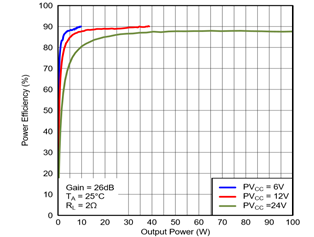
Figure 2 TPA3116 Efficiency Curve
2 Overview of SCT12A3 Output Adaptive Optimization (AAO)
Figure 3 shows the typical application circuit of the SCT12A3. The SCT12A3 can automatically adjust the output voltage based on the output current, and there are two able output voltages, VOUT1 and VOUT2, as shown in Figure 4. When the system load is light, the SCT12A3 output voltage is the FB terminal set voltage VOUT1. When the PA requires an increase in BOOST output power, the SCT12A3 determines whether to increase the output voltage to VOUT2 based on its own output current.
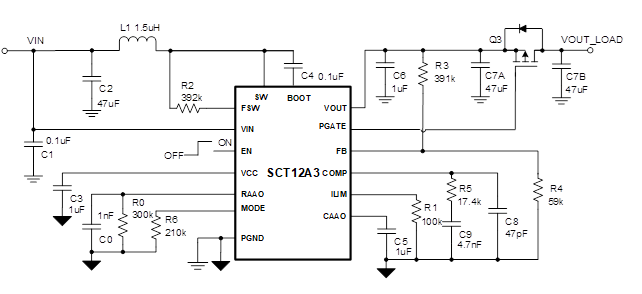
Figure 3 Typical Application of SCT12A3
As shown in Figure 4, the RAAO and MODE pins are used to set the relationship between AAO's corresponding input current threshold and VOUT2 and VOUT1. VOUT1 is set by an external voltage divider network R3, R4. When BOOST is started, the output is VOUT1. After the output is stable, the SCT12A3 determines the output current. If the output current is greater than the threshold set by RAAO, the output voltage will jump from VOUT1 to VOUT2.
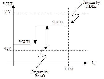
Figure 4 BOOST Output Voltage Vs. Output Current
The calculation formula for RAAO is as follows:
|
R_AAO=(1000000*Vin)/(V_out1*I_out) |
(1) |
Figure 5 shows the relationship curve between the typical input and output, RAAO, and output current. Different input voltages and outputs will correspond to different curves, so actual calculations are required when applying.
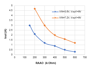
Figure 5 Output Current Vs. RAAO Resistance Value
The relationship between VOUT2 and VOUT1 is determined by the resistance value on the MODE pin. According to the MODE pin resistance value ion in Table 1, set the relationship between VOUT2 and VOUT1.
Table 1: MODE Resistance Value Selection Reference Table

For example, set VOUT1=9V, VOUT2=13.5V, and the output current jump threshold is 1.2A. Choose MODE 120kOhm, RAAO=300kOhm. Figure 6 shows the actual measurement curve. According to the change in output power, the response from VOUT1 to VOUT2 rises very quickly, with a response time of less than 300us, thus not affecting sound quality. When the load becomes lighter, after a certain delay, the decrease of VOUT2 decreases slowly to ensure that the auditory effect is not affected. This delay is set by the CAAO pin capacitor, with CAAO providing a ging current of 1uA, and a 1uF capacitor setting a delay of 1.5s.
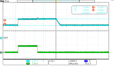
Figure 6 SCT12A3 Adaptive Output Regulation
3 Comparative Test of SCT12A3 Battery Life in Bluetooth Speakers
A comparative test of battery life using the SCT12A3 was conducted in a commercially available speaker, which is a 2 X 8W specification, powered by a single 2700mAh lithium battery, and the PA using TPA3116.
Test conditions: VOUT1=5.4V, VOUT2=10.8V, output current flip threshold 0.4A.
SCT12A3 settings: RAAO=560kOhm, CAAO=1uF, MODE=330kOhm
Test music: "Hotel California"
Figure 7 shows the output voltage of the SCT12A3 throughout the entire music. Depending on the amplitude of the music audio signal, the SCT12A3 output freely switches between VOUT1 and VOUT2.
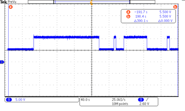
Figure 7 SCT12A3 Output Voltage
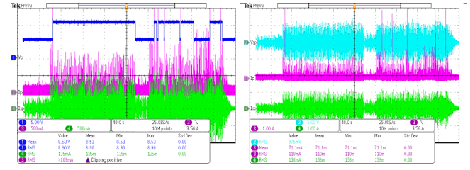
Figure 8 SCT12A3 with AAO, PA, and Speaker Input Voltage and Current
Figure 9 shows the output voltage of the SCT12A3 without AAO and the PA input current Ip, and speaker input current Isp. Comparing Figure 8 and Figure 9, with the AAO output function of the SCT12A3, the effective input power of the PA is reduced by 40%, thus the battery life is inevitably increased.

Figure 9 SCT12A3 without AAO, PA, and Speaker Input Voltage and Current
A burn-in test was conducted using the music "Hotel California":
· SCT12A3 without AAO output function, the standby time of the speaker is 11 hours and 15 minutes.
· SCT12A3 with AAO output function, the standby time of the speaker is 16 hours.
Therefore, the SCT12A3 AAO output function can greatly extend the battery life, up to 40%.
4 References
1) SCT12A3 Product Datasheet
2) SCT12A3 EVM User Manual
 Return

 京公网安备 11010802042628号